grid kit
contents
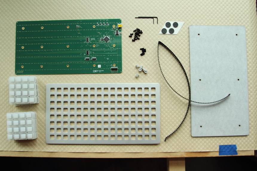
each grid kit contains the following:
- metal faceplate
- grid pcb
- laser cut acrylic backplate
- 8 keypads
- 128 diodes
- 4 adhesive backed rubber feet
- 15 button head cap screws
- 6 hex standoffs
- 6 set screws
- 1/16” hex wrench
- 0.05” hex wrench
you will need to source your own leds. see below for recommendations.
required tools
in order to successfully build the kit you will need:
- soldering iron
- solder
- solder wick (size #2 is best)
- fine-tipped tweezers like these.
##choosing leds
the easiest solution is to use the yellow/orange leds from the 2013/14 edition grids & euro modules: APL3015SYCK-F01, digikey: 754-1114-1-ND.
other suggested leds:
- green: wurth 150080GS75000
- red: osram LS T67B-T1U1-1-Z
- blue: QT QBLP676-IB
- white: greyscale monome leds. super bright (see note below): CLM3C-WKW-CWBYA453
if you’d like to select your own colours, follow these selection guidelines:
- packaging: ‘Cut Tape’ or ‘Cut strip’ for low quantities.
- millicandela rating (‘mcd’): 300-2500mcd. higher values are brighter.
- forward voltage (Vf): less than 3.2v. higher may work but is untested.
- viewing angle: as high as possible. wider (> 100 degrees) looks best.
- package/case: 2-SMD Flat lead, 1205, 1206, 1208 are recommended. 2-SMD Jlead, 2-PLCC are harder to solder. 0805 are small but easy to solder.
construction
after you’ve received your grid kit and leds you’ll be ready to start assembling.
soldering
orientation
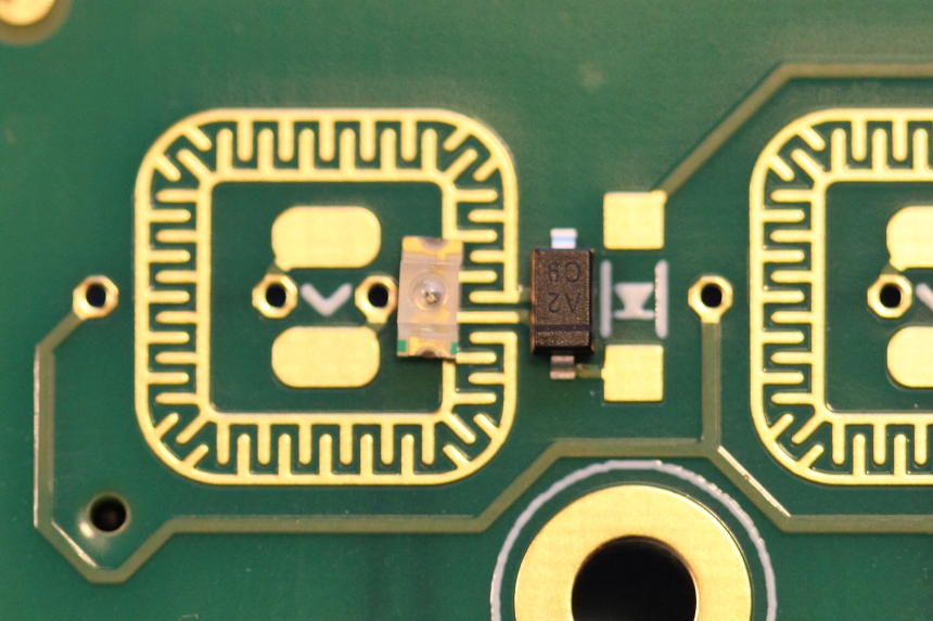
it is essential that you carefully orient the diodes and leds in your grid kit. the arrows on the pcb point toward the cathode which is represented by a line, green dot, or notch on the surface mount parts. if in doubt check the datasheet for your chosen leds.
#solder the diodes
start by soldering all the diodes as they are easier and will get you comfortable with surface mount parts.
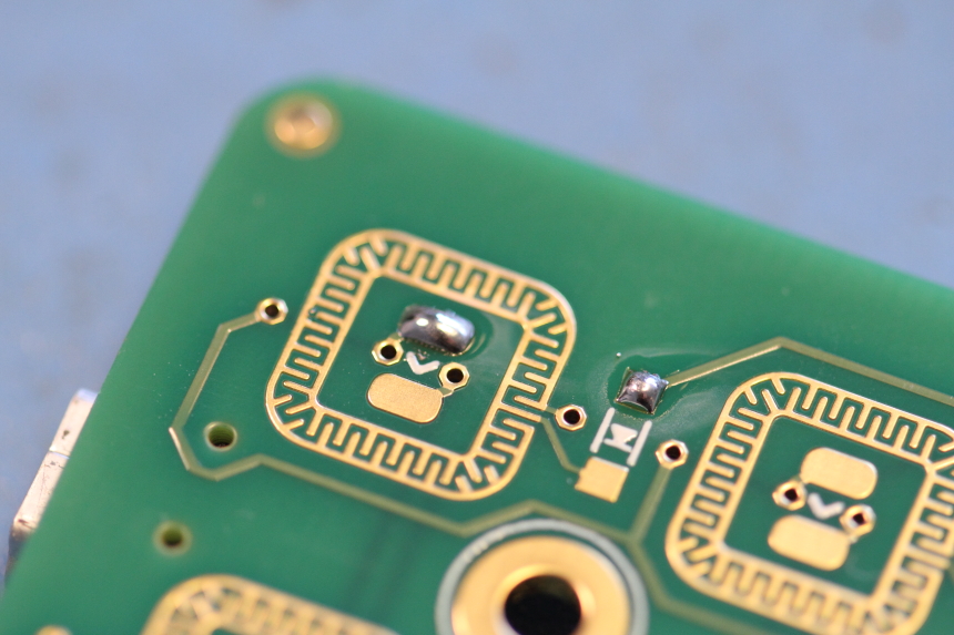
add a dot of solder onto one of the pads
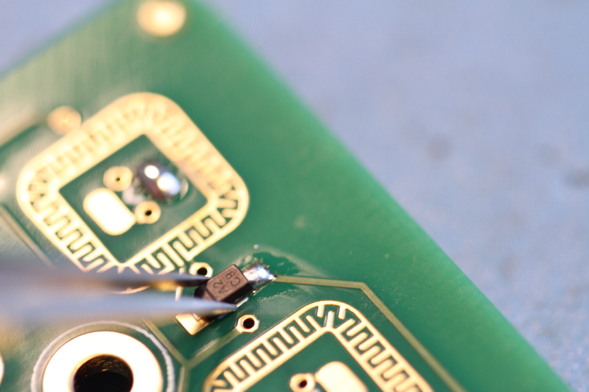
pick up a diode with the tweezers, taking care to orient it correctly. reheat the solder on the pad and push the diode into place. remove the soldering iron while holding the diode until the solder solidifies. now solder the other side by heating the gold pad with the iron and touching another dot of solder.
solder the leds
after you’ve completed all the diodes, you can start soldering the leds.
start with the led in the corner closest to the USB port, making certain to check the orientation.
before continuing, test the orientation is correct by plugging the grid into a powered usb port. you should see the led blink.
after confirming the first led is working correctly, you can attach the remainder of the leds.
removing solder from the star pattern
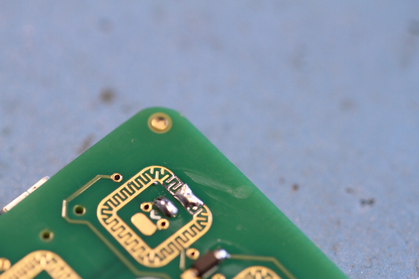
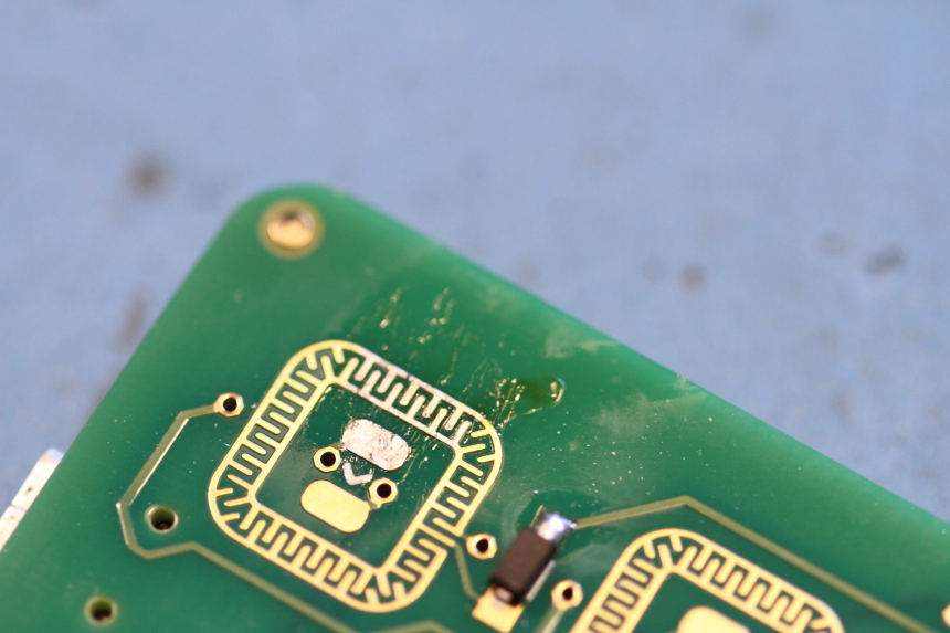
it’s likely that in the process you will get some solder on the star pattern that detects key presses. these will need to be removed or those keys will not function properly.
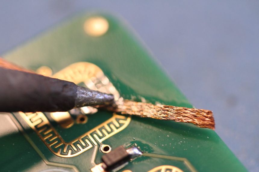
hold your solder wick on top of the affected area. heat up the solder wick using the side of the iron tip. you should see the solder melt and spread out into the wick. if you’re having trouble removing a small blob, you can add a little more solder to help the wicking process.
hardware assembly
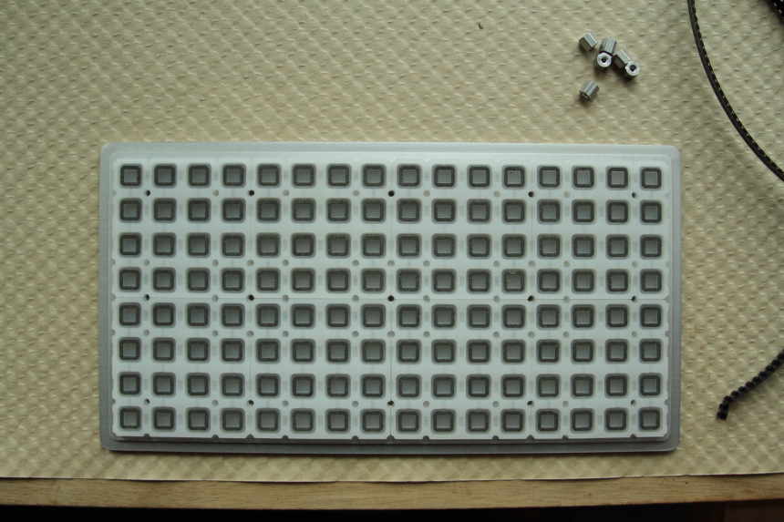
push the keypads into the plate. there are small indents between the keypads where the diodes are recessed. make sure these are all lined up ‘vertically’ like the diodes.
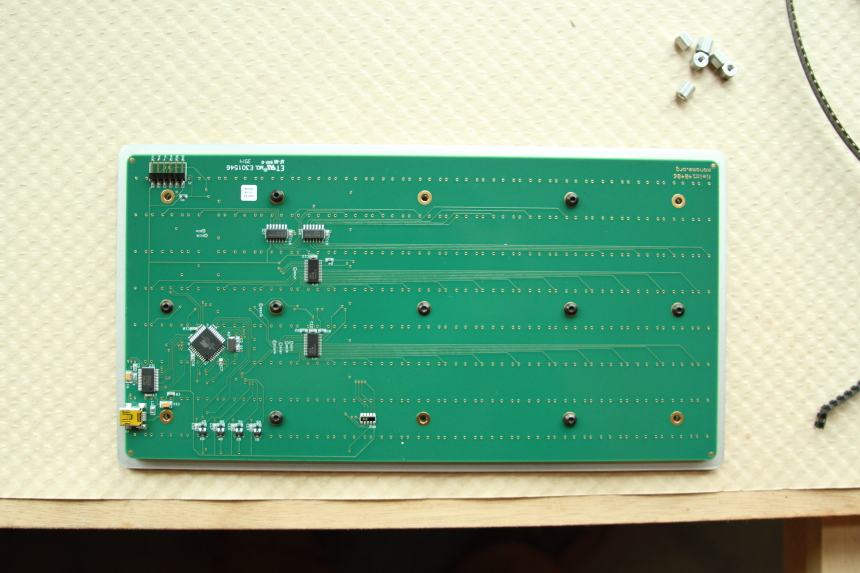
place the circuit board on top and using the 1/16” wrench add 9 of the screw caps as shown. you need to leave spaces for where the backplate is attached. no need to screw these in too tight.
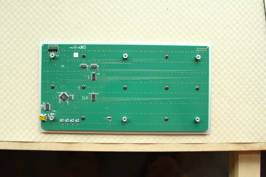 using the .05” wrench, attach the set screws to the remaining 6 holes. then screw on the hex standoffs until they’re finger tight.
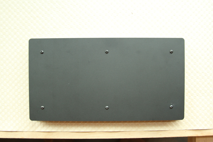 peel the protective backing off the acrylic backplate. using the remaining 6 screws, attach the backplate to the hex standoffs.
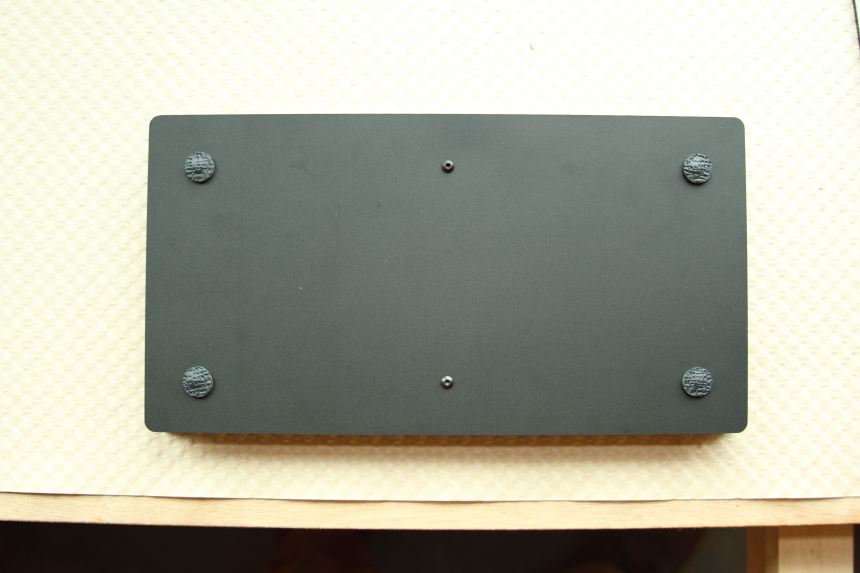 peel the rubber feet off their adhesive backing and attach them over the 4 outside screws.
note: it’s best to test your device beore attaching the rubber feet as they’re hard to remove. after you’ve confirmed all leds and button presses are working, then add the feet.
complete
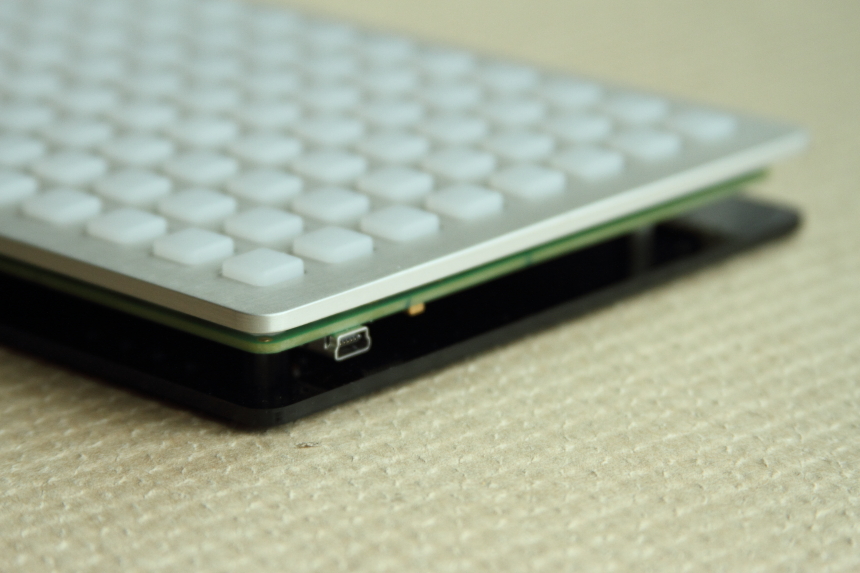
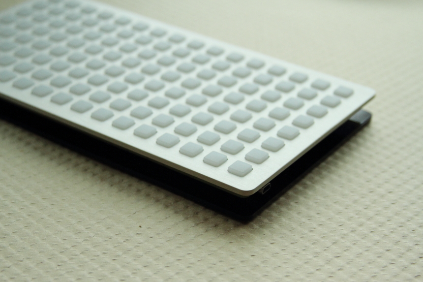 the grid kit is complete!
the kit is already programmed and ready to be used with a eurorack module, aleph or computer. if this is your first time using a grid with your computer, head to [[begin]] to install the drivers and get started with your new instrument.
led brightness
most people won’t need to do this step. however, if you use high-brightness leds you’ll likely want to decrease the brightness of the led drivers. you’ll need to change two resistors (R3 and R4) on the back of the pcb. they are shipped with a value of 2.2k ohms. we recommend 2.2k, 5k, and 10k values as a start. order at least 5 of each.
to change these resistors hold your soldering iron on it’s side against the resistor and add a blob of solder. the solder should flow on both sides of the part and the resistor will wipe away stuck to the end of your iron. wipe it off on your sponge and clean the pads with solder wick. resolder the resistors as for the leds and diodes though there is no specific orientation to the resistors.